
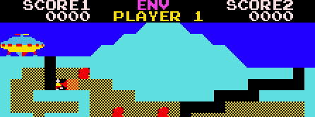


The Pit — Hardware
The Pit runs on Zilec Electronics' "roundup"-family board (MAME driver `taito/roundup.cpp`, machine `thepitu1`). The main CPU is a Zilog Z80 clocked at 3.072 MHz (18.432 MHz / 3 / 2), giving 50688 cycles/frame at a 60.606 Hz refresh; the native raster is 256×224, displayed rotated (MAME `ROT90`).
A second Z80 drives the sound hardware — two AY-3-8910 PSGs — receiving command bytes from the main CPU through the sound latch at `0xB800`.
Three hardware invariants matter when reading the map below: (1) a read and a write at one address can be different devices — `0xB800` reads the watchdog and writes the sound latch; (2) a read is not always pure — reading `0xB800` *kicks* the watchdog; (3) the LS259 control latch at `0xB000`–`0xB007` is bit-addressable — one address per bit, the data on d0.
Memory & I/O map
| Address | Name | Description |
|---|---|---|
| 0000:4fff | rom | Program ROM, 20480 bytes (`thepitu1` main-CPU parts p38b.ic38 + p39b.ic39 + p40b.ic40 + p41b.ic41 + p33b.ic33) |
| 8000:87ff | workRam | Work RAM (see Work RAM) |
| 8800:8bff | colorRam | Colour RAM, per-tile colour; mirror at 0x8c00-0x8fff |
| 9000:93ff | videoRam | Video RAM / tilemap, 0x20-wide rows; mirror at 0x9400-0x97ff |
| 9800:983f | attrRam | Attribute RAM: per-column (×2) vertical scroll — column N scrolls by attrRam[N*2] |
| 9840:985f | spriteRam | Sprite RAM, 8 sprites × 4 bytes; the NMI copies the 0x8220 staging block here each frame |
| a000 | in0 | R: IN0 joystick + dig/fire, active-low, LS157-muxed with cocktail IN2 by mainLatch b6 then complemented. W: nop (not hooked up) |
| a800 | in1 | R: IN1 coin + start, active-high |
| b000 | dsw | R: DIP switches (the read side of address b000) |
| b000 | mainLatch | W (b000-b007): the LS259 control latch — NMI enable, coin-lockout, sound-enable, flip-X + IN0/IN2 mux, flip-Y (bit table below) |
| b800 | soundLatch | W: sound command byte to the sound CPU |
| b800 | watchdog | R: watchdog reset — the read is the kick, the returned byte is discarded |
IN0 — joystick + dig/fire (read at 0xA000, active-low then complemented)
The read at `0xA000` is muxed (mainLatch b6 selects the IN0 upright port vs the IN2 cocktail port) and complemented, so the ROM works on the active-high form: idle reads `0x00`, a pressed bit reads 1.
| Bit | Mask | Input |
|---|---|---|
| 0 | 0x01 | Left |
| 1 | 0x02 | Right |
| 2 | 0x04 | Down |
| 3 | 0x08 | Up |
| 4 | 0x10 | Dig / fire (BUTTON1) |
IN1 — coin / start (read at 0xA800, active-high)
| Bit | Mask | Input |
|---|---|---|
| 0 | 0x01 | Coin |
| 1 | 0x02 | Start 2P |
| 2 | 0x04 | Start 1P |
LS259 control latch (write 0xB000–0xB007, one address per bit, data on d0)
The latch is an 8-bit LS259 addressable latch (IC42): each of the eight addresses `0xB000`–`0xB007` sets its own bit from data bit 0.
| Address | Bit | Line |
|---|---|---|
| b000 | 0 | NMI mask / enable (the main loop writes 1 to arm the vblank NMI) |
| b002 | 2 | Coin lockout |
| b003 | 3 | Sound enable |
| b006 | 6 | Flip-X + IN0/IN2 input-mux select (cocktail) |
| b007 | 7 | Flip-Y |
Sprite record format (4 bytes each, staged at 0x8220, copied to 0x9840)
Sprite RAM holds 8 sprites of 4 bytes each. Each record decodes as: byte0 → screen position on one axis; byte1 → tile `code & 0x3f` plus flip-X (0x40) / flip-Y (0x80); byte2 → `color = (byte2 & 7) * 4` plus a priority bit3 (a set bit3 draws the sprite over high-priority background); byte3 → the other screen axis. Under the display's upright (ROT270) view, byte0 is the screen-horizontal coordinate and byte3 the screen-vertical.